Smartphone without a battery
How to wire and run an old smartphone without a battery.
Intro
I have an old Samsung Galaxy S5 that I wanted to use to run my 3D printer. There is a great project called octo4a that runs OctoPrint on Android devices.
Using an old smartphone for OctoPrint is a perfect fit - it has USB OTG support to connect to the printer, WiFi to access the controls and upload models, and a camera to monitor the print progress. The only, yet critical, issue is that the kernel for Galaxy S5 does not support charging while it's connected to a USB device. The battery is old and worn, and cannot last through several hours of printing.
The approach I took was to build a "fake battery" circuit that emulates the battery, but is powered by 5V via USB.
Process
First, I removed the battery. Luckily, this smartphone is old enough to have user-serviceable battery compartment.
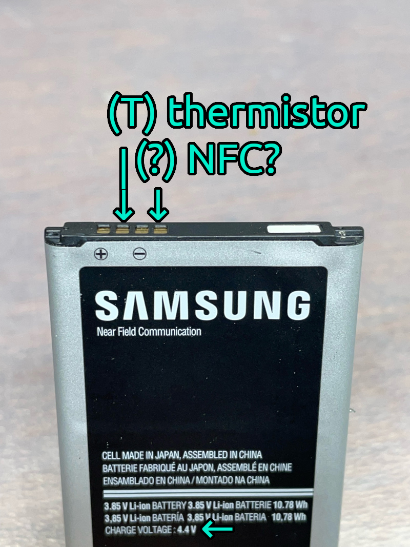
Older batteries might have only two terminals, (+) and (-). Newer batteries might have three or four terminals. I measured voltage and resistance between all terminals to find out what they might be.
These are the results:
- Terminals (+) and (-) are obvious. Generally, Li-ion battery will produce 3.4V when almost-empty and 4.2V when full. The battery also says "CHARGE VOLTAGE 4.4V", so that voltage level at the battery terminal would not cause any issues with the smartphone.
- The second terminal is the thermistor (T), used to get the approximate temperature of the battery. The resistance between (T) and (-) is around 2350ohm at room temperature. Being a safety feature, my smartphone will not start at all if the thermistor terminal is not connected.
- The fourth terminal is most likely used for NFC (which is a part of the battery). It's not going to be used.
So what I need my "fake battery" circuit to do is:
- Provide 3.4-4.4V between (+) and (-) battery terminals on the smartphone
- Create ~2350ohm resistance between (T) and (-)
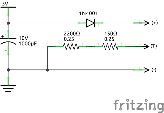
Since I am still powering the smartphone from a 5V USB power supply, I can add a single silicon diode between the power supply's +5V and (+) battery terminal to drop the incoming voltage by ~0.7V down to ~4.3V, which is within the range that the smartphone can expect.
IMPORTANT: Voltage drop across the silicone diode depends on the current, and multimeter measurements might not be accurate. See "Diode voltage drop" at the bottom of the page.
To get ~2350ohms, I connected a 2200ohm and a 150ohm in series. A variable resistor of appropriate range might work too.
This setup works, and the smartphone powers up. However, it can draw plenty of current and needs a fairly powerful power supply. Basic phone charger <1A USB power supply was not enough to even finish booting, but a ~2A was enough to boot and launch octo4a. Even after booting, if the smartphone is under higher load (initializing the USB connection, using the camera), it draws more current, and will abruptly power off if the current draw exceeds what power supply can provide.
To help address these issues:
- Add a 1000uF capacitor between (+5V) and (ground) on the circuit. See "Capacitors" at the bottom of the page for warnings and ideas.
- Turn on the Battery Saver in Android and set it up to automatically turn on if estimated battery level is below 75% (just in case). This seems to lower the processing power enough to avoid shutdowns.
- In OctoPrint settings, either disable the camera entirely, or use it at the lower-end FPS and resolution (320x240 @5FPS). Camera has occasionaly caused octo4a to crash, so I ended up disabling it anyway.
Schematic
In ASCII:
(+5V)
  |
  |          silicon diode
  +---------------|>|------(+)
  |
  |        +---[2350ohm]---(T)
  | 1000uF |
  +---||---+---------------(-)
           |
        (ground)
As an image:
Result
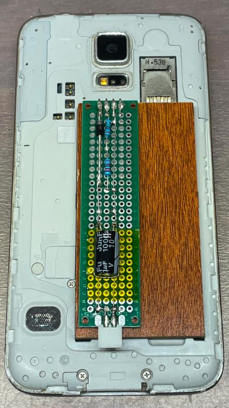
I cut and sanded a piece of flooring to fit into the battery compartment. Then, built and soldered the circuit on a through-hole prototype board and mounted it on top of that with double-sided tape. The 4 pins on the top are bent inward, fit into small grooves in the base and make good contact with the springy terminals of the battery compartment. (I could have just soldered the wires directly to the terminals, but wanted to make this device removable just in case I would ever need the battery again). Power comes through the JST connector at the bottom. (I salvaged a long USB cable with a broken micro-USB plug, so I decided to use JST connectors instead of USB for power).
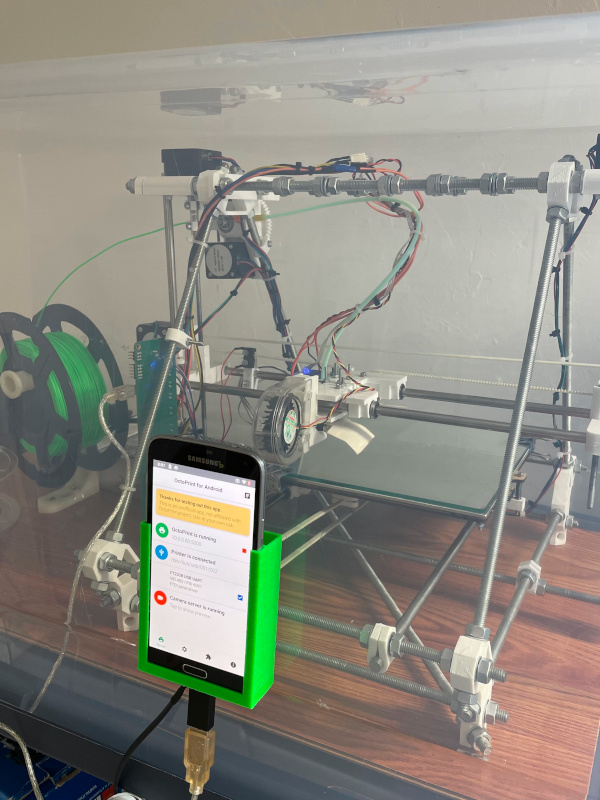
3D printer (old RepRapPro) in its enclosure (storage box) and its brain (Samsung Galaxy S5) in a 3D-printed holder. Super modern and high-tech, I know.
This setup has been working fairly well for me for a few weeks now.
Additional info
Diode voltage drop
Voltage drop across the diode depends on the current. If you connect the diode, but do not connect the circuit to anything, and try to measure the "final" voltage (after the diode) with a multimeter, you will get somewhere around ~4.8V, because the current running through the multimeter is miniscule. You might think you need 4 diodes to bring the voltage down sufficiently, but you do not, one is enough.
Diagrams:
Circuit without load, measured with a multimeter:
(+5V)
  |  diode
  +---|>|---+ <--+
                 |
          [multimeter: 4.8V]
                 |
  +---------+ <--+
  |
(ground)
Circuit with load (connected to the smartphone):
(+5V)
  |  diode
  +---|>|---+ <-------------+
            |               |
       [smartphone]  [multimeter: 4.2V]
            |               |
  +---------+ <-------------+
  |
(ground)
Capacitors
It might be possible to use a lower-current power supply by replacing the 1000uF capacitor with several "supercapacitors" (5F and above). The only issue I see is that the initial power-up will stress the power supply since empty capacitors are essentially a short circuit.
References
Adafruit - about Li-ion and LiPoly batteries