Solar-charged LED flasher
Neat, simple, and theoretically eternal electronic circuit.
Can be powered by a solar panel and a large capacitor, or a single 1.5V battery.
The LED flashes (fairly brightly) approximately once every 3 seconds.
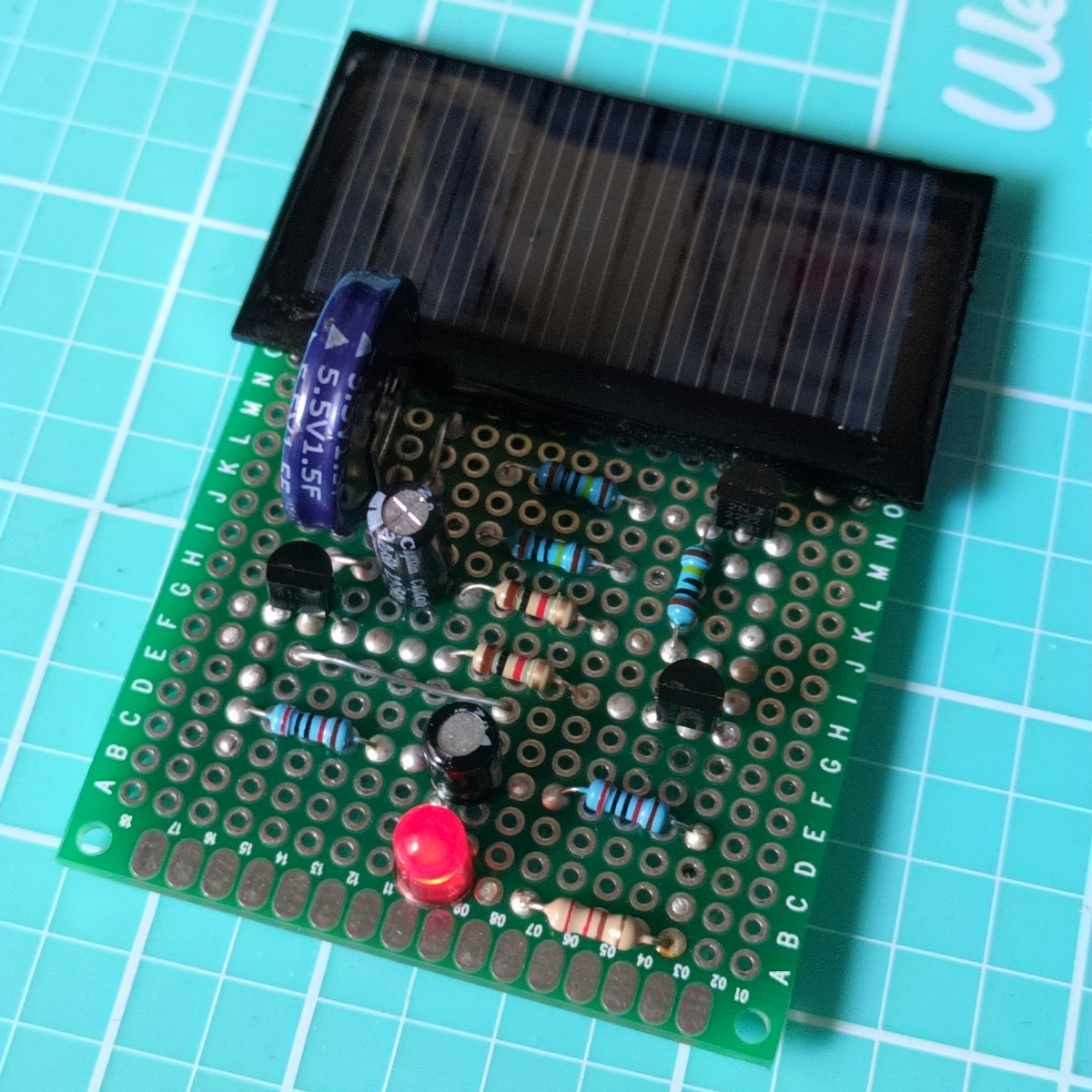
Final version soldered on protoboard.
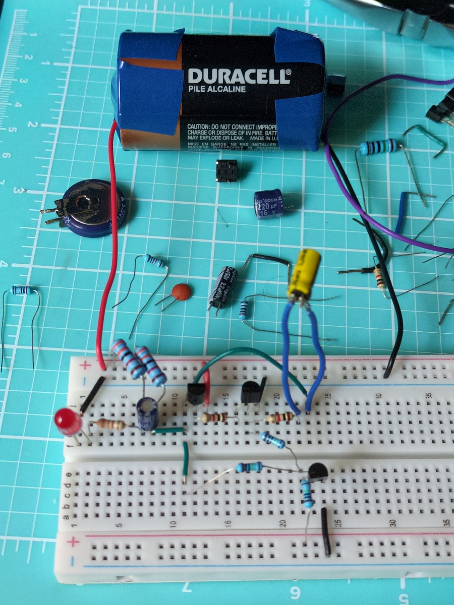
Battery-powered prototype on breadboard.
How?
Looking through my old bookmarks, I found this neat LED flasher circuit:
I tried building the same circuit, but the LED was very dim when blinking, or the circuit did not behave the way I expected. So I re-built it from scratch to understand how it works, and what I can update. I understood most of it, although not entirely.
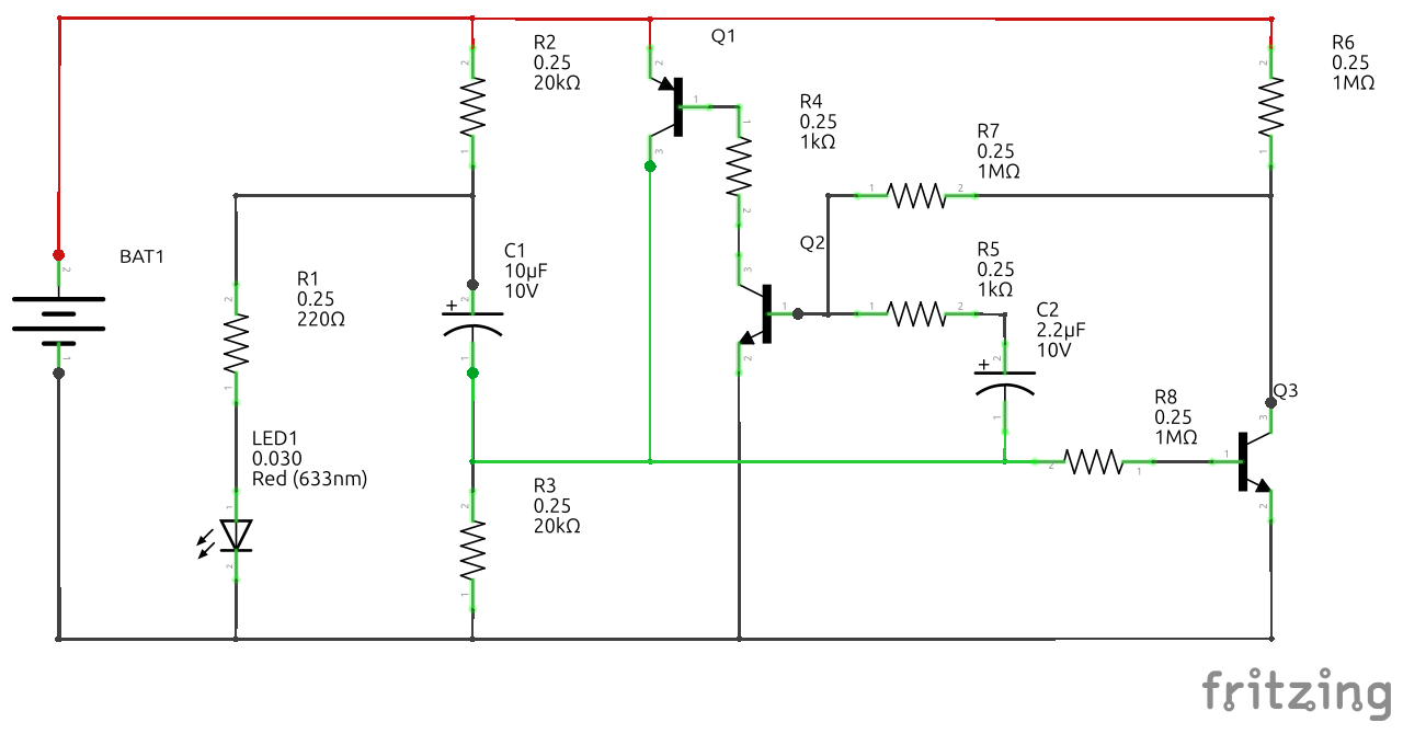
Schematic I ended up building, with values that worked for me.
It is the same circuit as the Infinite Firefly, but re-drawn to be easier to understand (for me, at least), and using fewer and more common resistor values.
Some notes:
- The battery is substituted with a solar cell and a large capacitor in parallel.
- R1 is the current limiting resistor for the LED, which can be adjusted for brightness.
- R2 and R3 should be in the ten thousands Ohm range, 10k, 20k, 33k should work.
- R4 seems to affect the brightness of the LED flash, but I am not sure as to why. Original calls for 100KOhm, but the flash is much brighter with 1KOhm.
- C1 could be lower, 4.7uF or even 2.2uF. C1 is discharged for such a brief period, it does not lose much charge.
- C2, R5, R6, R7, R8 control the flashing frequency. Lower capacitance or lower resistance = faster flashing. Using 1MOhm for R6, R7, R8 works well, but original calls for 20MOhm and a much smaller capacitor.
How does it work?
To the best of my knowledge - the video linked by moonworm explains a bit.
Looking at the schematic above, from left to right:
- Battery BAT1 is a single 1.5V cell.
- LED and a current limiting resistor R1 is a standard way to connect and power a LED.
- However, It is not possible to light a LED from a single 1.5V battery directly - even red LEDs have a forward voltage of 1.5-2.0V. But this circuit uses an interesting approach to temporarily supply a higher voltage.
- First, circuit charges C1 through R2 and R3. C1 eventually reaches 1.5V between its positive and negative terminals.
- Then, if the circuit can somehow connect battery's positive terminal to C1's negative terminal, we end up with an equivalent of two batteries in series, 1.5V + 1.5V = 3.0V, which is enough to light a LED (until C1 discharges).
- To do so (connect battery's +1.5V to C1's negative terminal), the circuit uses PNP transistor Q1. PNP transistors are normally used on the high side of the circuit. To open ("enable") a PNP transistor, its base pin must be pulled to ground.
- To pull Q1's base pin to ground, the circuit uses a NPN transistor Q2. R4 is a current-limiting resistor to avoid a short between Q1's base pin and ground.
- Now, the circuit can start the LED flash by pulling Q2's base pin high, and stop it by pulling the Q2's base pin low. So the circuit needs some sort of oscillation.
(This is where I started getting lost.)
- When LED is off (Q1 is closed), capacitor C2 is being (slowly) charged through R6, R7, R5, R3.
- When C2 reaches 0.7V, it opens Q2, which opens Q1.
- When Q1 is open, the circuit puts 1.5V + 0.7V = 2.2V (battery + C2) on Q2's base pin, keeping it open, and also puts 1.5V through R8 to Q3's base pin, opening it.
- When Q3 is open, it drains C2 through R7 and R5.
- C2 reaches <0.7V, closing Q2, which closes Q1
Why?
For fun!